Air Probe Dimensional Data-Single Master – series 60 – 80

Clearance recommendations Series 60 thru 80
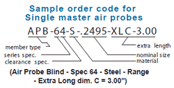
Clearance values for single mastered gaging members are referenced to the nominal master sizes. Users should pick clearances that allow the probe to enter the workpieces at their maximum material condition, and at the same time, not have excessive clearance at the minimum material condition. To determine the body size of a single master air probe, subtract the clearance value shown from the nominal master ring. For air ring gages, add the value shown to the nominal setting master.
| Guide lines for clearances are as follows: | |
|---|---|
| Product tolerance | WGC specs. |
| .00001″-.00012″ (.2µ – 3µm) | 62, 71 |
| .00012″- .0004″ (3µ – 10µm) | 63, 72 |
| .0004″ – .0020″ (10µ – 50µm) | 64, 73 |
| .0020″ – .0040″ (50µ -100µm) | 65 |
Best accuracy will always be obtained with single mastered gages by mastering near the middle of the product tolerance.

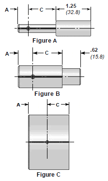
AIR PROBE DIMENSIONAL DATA, Series 60, 70, & 80
| Air probe body dimensions ( inches / millimeters ): | ||||||
| Size |
Dimension A | Available Series |
||||
| above -incl. | APT | APB | APS | Dim. C | Figure | |
| .059 – .073 1.50 – 1.85 |
.190 4.83 |
.080 2.03 |
.050 1.27 |
.625 15.88 |
A | 70 |
| .073 – .120 1.85 – 3.05 |
.190 4.83 |
.080 2.03 |
.050 1.27 |
.625 15.88 |
A | 70 |
| .120 – .18 3.05 – 4.65 |
.250 6.35 |
.085 2.16 |
.065 1.65 |
.750 19.05 |
A | 60 & 70 |
| .183 – .300 4.65 – 7.62 |
.375 9.53 |
.095 2.41 |
.075 1.91 |
1.000 25.40 |
A | 60 & 70 |
| .300 – .485 7.62 – 12.32 |
.440 11.18 |
.095 2.41 |
.075 1.91 |
1.000 25.40 |
A | 60, 70 & 80 |
| .485 – .860 12.32 – 21.84 |
.500 12.70 |
.095 2.41 |
.075 1.91 |
1.000 25.40 |
B | 60, 70 & 80 |
| .860 – 2.510 21.84 – 63.75 |
.750 19.05 |
.095 2.41 |
.075 1.91 |
1.000 25.40 |
B | 60, 70 & 80 |
| 2.510 – 5.865 63.75 – 148.97 |
.875 22.23 |
.105 2.67 |
.085 2.16 |
1.000 25.40 |
C | 60, 70 & 80 |
| 5.865 – 8.260 148.97 – 209.80 |
1.062 26.97 |
.125 3.17 |
.105 2.67 |
1.000 25.40 |
C | 60 & 80 |
| Air probe body clearances (inches / micrometers): | |||||
| Size | Clearance class | ||||
| above – incl. | 1 | 2 | 3 | 4 | 5 |
| .059 – .120 1.50 – 3.05 |
.00015 3.81 |
.0003 7.62 |
.0004 10.16 |
—- | —- |
| .120 – .183 3.05 – 4.65 |
.00015 3.81 |
.0003 7.62 |
.0004 10.16 |
.0006 15.24 |
.0010 25.40 |
| .183 – .246 4.65 – 6.25 |
.00015 3.81 |
.0003 7.62 |
.0005 12.70 |
.0008 20.32 |
.0018 45.72 |
| .246 – .300 6.25 – 7.62 |
.0002 5.08 |
.0004 10.16 |
.0006 15.24 |
.0010 25.40 |
.0022 55.88 |
| .300 – .485 7.62 – 12.32 |
.0002 5.08 |
.0004 10.16 |
.0006 15.24 |
.0012 30.48 |
.0026 66.04 |
| .485 – .540 12.32 – 13.72 |
.0003 7.62 |
.0004 10.16 |
.0007 17.78 |
.0014 35.56 |
.0030 76.20 |
| .540 – 1.510 13.72 – 38.35 |
.0003 7.62 |
.0004 10.16 |
.0008 20.32 |
.0016 40.64 |
.0030 76.20 |
| 1.510 – 3.010 38.35 – 76.45 |
—- | .0005 12.70 |
.0009 22.86 |
.0018 45.72 |
.0030 76.20 |
| 3.010 – 4.510 76.45 – 114.55 |
—- | .0006 15.24 |
.0010 25.40 |
.0020 50.80 |
.0030 76.20 |
| 4.510 – 6.510 114.55 – 165.40 |
—- | —- | .0012 30.48 |
.0022 55.88 |
.0034 86.36 |
| Jet data & fittings: | ||
| Series | Jet dia. | Fitting |
| 60 | .048 | .375-32 UNEF |
| 70 | .023 | .281-40 UNS |
| 80 | .094 | .375-32 UNEF |
| 1 Ser. 60 not available in sizes below .120″ (3.05mm). | ||
| 2 Ser. 80 not available in sizes below .360″ (9.14mm). | ||
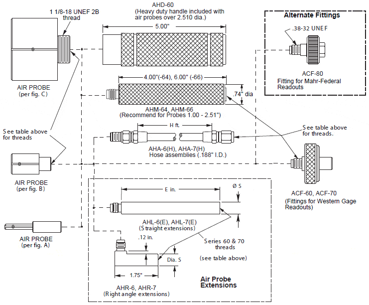
Accessories for Air Probe – Single Master – Series 60 thru 80
| AIR GAGE SERIES |
THREAD SIZE |
Ø S | (HOSE ASSY PART NO.S) | (PROBE EXTENTION PART NO.S) | |||
| DIM H = 3 ft. | DIM H = 5 ft. | DIM E = 2 in. | DIM E = 4 in. | DIM E = 6 in. | |||
| 60 | .38-32 UNEF | .485″ | AHA-63 | AHA-65 | AHL-62 | AHL-64 | AHL-66 |
| 70 | .28-40 UNS | .360″ | AHA-73 | —- | AHL-72 | AHL-74 | —- |
| 80 | .38-32 UNEF | .485″ | AHA-63 | AHA-65 | AHL-62 | AHL-64 | AHL-66 |

SERIES 60 THRU 80
AHA-63 Hose ass’y, 3 ft -.38-32 UNEF
AHA-65 Hose ass’y, 5 ft -.38-32 UNEF
AHA-66 Hose ass’y, 6 ft – .38-32 UNEF
AHA-73 Hose ass’y, 3 ft -.28-40 UNS
AHL-62 Handle/ext., 2 in x .38-32 UNEF
AHL-64 Handle/ext., 4 in x .38-32 UNEF
AHL-66 Handle/ext., 6 in x .38-32 UNEF
AHL-72 Handle/ext., 2 in x .28-40 UNS
AHL-74 Handle/ext., 4 in x .28-40 UNS
AHD-60 Heavy duty handle 6″ x Ø 1.20″
AHM-64 Medium duty handle 4″ x Ø .74″
AHM-66 Medium duty handle, 6″ x Ø .74″
AHR-6 Rt. Angle adapter, .38-32 UNEF
AHR-7 Rt. Angle adapter, .28-40 UNS
REPAIR PARTS
AOR-10 O-ring kit for series 60, 10 pcs
AOR-07 O-ring kit for series 70, 10 pcs
READOUT FITTINGS
ACF-60 Fitting, use on: Milli Check, Micro Air – Ser.60
ACF-70 Fitting, use on: Milli Check, Micro Air – Ser.70
ACF-80 Fitting, use on Mahr-Federal Readouts

