Gage accuracy can be no better than the precision of the standards used for calibration.
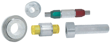


Setting Master Dimensional Data
See page 27 for order codes
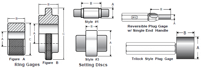
| Ring Gage Masters | ||||
| Diameter A above -incl. |
Dia. C |
Dim. B |
Gage Blank # |
Figure |
| .040 – .060 .060 – .070 .070 – .230 .230 – .365 .365 – .510 .510 – .825 .825 -1.135 1.135 -1.510 |
.94 .94 .94 1.13 1.38 1.75 2.13 2.50 |
.19 .25 .37 .56 .75 .94 1.13 1.31 |
00** sp** 0** 1 2 3 4 5 |
A A A A A A A A |
| 1.510 – 2.010 2.010 – 2.510 2.510 – 3.010 3.010 – 3.510 3.510 – 4.010 |
4.00 4.50 5.00 5.50 6.38 |
1.50 1.50 1.50 1.50 1.50 |
6 7 8 9 10 |
B B B B B |
| 4.010 – 4.760 4.760 – 5.510 5.510 – 6.260 6.260 – 7.010 7.010 – 7.760 7.760 – 8.510 8.510 – 9.100 |
7.25 8.25 9.25 10.30 11.30 12.30 13.30 |
1.50 1.50 1.50 1.50 1.50 1.50 1.50 |
11 12 13 14 15 16 17 |
B B B B B B B |
| ** In these sizes, Western provides a blank that is thicker than the A.N.S.I. standard for more reliable gage mastering. | ||||
| AMERICAN GAGE DESIGN TOLERANCES | |||||
| Size above-incl. inch / mm |
Tolerance – inch / µm | ||||
| XXX | XX | X | Y | Z | |
| .029 – .825 .74 – 20.96 |
.00001 .25 |
.00002 .51 |
.00004 1.02 |
.00007 1.78 |
.00010 2.54 |
| .825 – 1.510 20.96 – 38.35 |
.000015 .38 |
.00003 .76 |
.00006 1.52 |
.00009 2.29 |
.00012 3.05 |
| 1.510 – 2.510 38.35 – 63.75 |
.00002 .51 |
.00004 1.02 |
.00008 2.03 |
.00012 3.05 |
.00016 4.06 |
| 2.510 – 4.510 63.75 – 114.55 |
.000025 .64 |
.00005 1.27 |
.00010 2.54 |
.00015 3.81 |
.0002 5.08 |
| 4.510 – 6.510 114.55 – 163.35 |
.000033 .83 |
.000065 1.65 |
.00013 3.30 |
.00019 4.83 |
.00025 6.35 |
| 6.510 – 9.010 163.35 – 228.85 |
.00004 1.02 |
.00008 2.03 |
.00016 4.06 |
.00024 6.10 |
.00032 8.13 |
| Set Disc Masters | ||
| Diameter A above -incl. |
Dim B |
Gage Style |
| .150 – .230 .230 – .365 .365 – .510 .510 – .825 .825 – 1.135 1.135 – 1.510 1.510 – 2.510 2.510 – 8.010 |
1.19″ 1.31″ 1.44″ 1.56″ 1.69″ 1.94″ .88″ 1.00″ |
1 1 1 1 1 1 3 3 |
| Master Setting Plugs | ||
| Diameter A above -incl. |
Dim B |
Gage Style |
| .060 – .825 .825 – .947 .947 – 1.135 1.135 – 1.510 1.510 – 2.010 2.010 – 3.510 3.510 – 8.010 |
2.00″ 1.25″ 1.37″ 1.50″ .88″ 1.00″ 1.00″ |
Reversible Trilock Trilock Trilock Trilock Trilock Trilock |
Bilateral / Unilateral Tolerances
A.G.D. classes define the total tolerance zone for the gage. Master gages are made with the A.G.D. class tolerance split equally (bilaterally). Go and NoGo fixed limit gages for functional testing of workpieces are normally unilaterally toleranced into the tolerance zone of the part. Thus, “Go Rings” and “No-Go Plug” gages are unilaterally minus toleranced. “No-Go Rings” and “Go Plug” gages are unilaterally plus toleranced. For example, a .5000″ master ring gage, with a class “XX” tolerance (.00002″) is finished to a diametrical tolerance of ±.00001″. Ordered as a No-Go ring gage, the .5000″ ring would be finished to +.00002″/.00000″ diametrical tolerance.

