The choice of air gage or inductive type requires evaluating how these sensors best fit the user’s application.
Air gage sensors
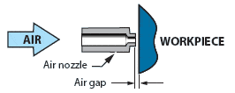
Air gage sensors measure the backpressure created when an air nozzle is brought in close proximity to the workpiece; the air gage readout measures this pressure and displays the dimensional change in the air gap.

Non contact – The air nozzle throttles the air at the point where the air exits the jet hole, thus the average height of a spot on the surface opposite the jet hole is sensed by the air readout. Since the nozzle does not contact the workpiece, wear does not directly effect the accuracy of the gage; more over, the pressure of the air has a self cleaning effect on the workpieces, making air gages perform exceptionally well in shop floor environments.
Sensor size – Air nozzles can be made with jet holes from .010″ to .100″ (.25 to 2.54 mm), with .050″ (1.25mm) being preferred for most applications. Multi-sensor gaging members are easily constructed by drilling inter-connecting air passages to gaging nozzles.
Gaging ranges – Air gages have relatively limited ranges. For good linearity, the gaging range of air gage member must be less than 8% of the jet hole size. For most applications, practical limits on air flow limit jet sizes to .079″ (2 mm) and gaging ranges to .006″ (.15 mm) or less. Furthermore, applications requiring exceptionally high accuracies, such as diametrical tolerance limits of .00008″ (.002mm), are best measured by air gage members designed for ranges .0006″( .015 mm) or less.
Response time – depends on the volume of the air circuit and the size of the gaging nozzles. Response times can vary from less than 100 milliseconds to several seconds; except for gages with very small jet sizes, typical response times will be less than two seconds.
Cost – Air gage nozzles are less expensive than LVDT gaging cartridges. For applications that require the summing of inputs from two or more sensors they are significantly less expensive than LVDT gaging.
LVDT sensors
LVDT sensors measure the voltage developed in wire coils as a magnetic core attached to a stylus is displaced by the test surface; changes in this voltage are displayed as dimensional changes.

Hard contact – LVDT gages with a spherical stylus sense a point on the contacted surface, or with a flat stylus tip, the highest point on the surface is sensed. Contact gaging is generally preferred for gaging rough surface finishes and narrow lands. Contact gages, particularly those with flat stylus tips, tend to be more sensitive to surface contaminants.
Sensor size – Compared to air gage nozzles, LVDT gaging cartridges are relatively large and expensive. Sizes vary from 6 to 8 mm diameter (.236″ to .315″) and from 35 to 85 mm (1.38″- 3.35″) in length. Multi-sensor applications are implemented by electronically interconnecting gaging cartridges at the readout instrument. The large size of LVDT sensors prohibit their use on internal diameters except for rather large bores. Gaging small bores requires the use of a motion transfer mechanism, adding to cost and decreasing the accuracy.
Gaging ranges – LVDT gages have significantly greater linear measuring range than air gages. Linearity of 1/2% over ± 1 mm (±.040″) gaging range is typical. Highest resolutions are obtained when the gaging range is less than .05 mm (.002″).
Response time – Depends only on the time constants of the readout. Response times as short as 1 millisecond can be obtained with suitable electronics. LVDT gages are preferred for automated gages with very short cycle times.
Cost – Generally more expensive than air gaging, except where the extended range capability reduces the number of gages required for the application. Use LVDT gages for applications requiring hard contact or where an extended gaging range is beneficial.
Surface finish effects – The air gage senses the average height of the surface while the contact gage senses the peaks of the surface, which can result in a variance between measurements made by these two types of sensors on rough surfaces. This variance will be minimal or nonexistent on a part with a ground or honed surface, but may be significant on a machined part with a rough surface finish. In general this will not exceed the difference between the center line average surface roughness of the workpiece and that of the setting masters used to zero the gages.

