Air Probe Dimensional Data – Dual Master – Series 10 – 50

Body clearances
Clearances for series 10 thru 50 air gage members are referenced to the maximum material condition of the feature to be inspected. Determine the body size of an air probe by subtracting the clearance value shown in the adjacent table from the minimum part size. For air ring gages, add the value shown to the maximum part size.
Clearance recommendations
Low clearance . . Class 1 — for the highest accuracy applications such as select fitting of valve spools and sleeves where finishing tolerance is less than .00016” (4.1 µm).
Standard clearance . . Class 2 — best for most applications. Members are furnished to this specification when no other specification is given.
Extra clearance . . Class 3 — for applications requiring extra gaging range such as grinding and honing operations where sizing information is required before the final size is obtained.

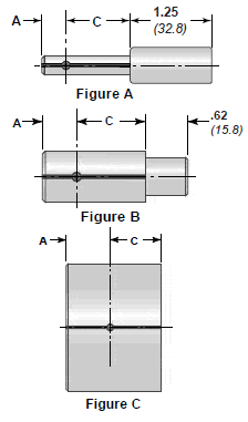
AIR PROBE DIMENSIONAL DATA, Series 10, 40, & 50
| Air probe body dimensions ( inches / millimeters ): | ||||||
| Size |
Dimension A | |||||
| above -incl. | APT | APB | APS | Dim. C | Fitting | Figure |
| .059 – .073 1.50 – 1.85 |
.190 4.83 |
.080 2.03 |
.050 1.27 |
.625 15.88 |
#10-32 UNF | A |
| .073 – .120 1.85 – 3.05 |
.190 4.83 |
.080 2.03 |
.050 1.27 |
.625 15.88 |
#10-32 UNF | A |
| .120 – .183 3.05 – 4.65 |
.250 6.35 |
.085 2.16 |
.065 1.65 |
.750 19.05 |
.25-28 UNF | A |
| .183 – .300 4.65 – 7.62 |
.375 9.53 |
.095 2.41 |
.075 1.91 |
1.000 25.40 |
.25-28UNF | A |
| .300 – .485 7.62 – 12.32 |
.440 11.18 |
.095 2.41 |
.075 1.91 |
1.000 25.40 |
#10-32 UNF | B |
| .485 – .860 12.32 – 21.84 |
.500 12.70 |
.095 2.41 |
.075 1.91 |
1.000 25.40 |
.25-28 UNF | B |
| .860 – 2.510 21.84 – 63.75 |
.750 19.05 |
.095 2.41 |
.075 1.91 |
1.000 25.40 |
.50-20 UNF | B |
| 2.510 – 5.865 63.75 – 148.97 |
.875 22.23 |
.105 2.67 |
.085 2.16 |
1.000 25.40 |
.50-20 UNF | C |
| 5.865 – 8.260 148.97 – 209.80 |
1.062 26.97 |
.125 3.17 |
.105 2.67 |
1.000 25.40 |
.50-20 UNF | C |
| Air probe body clearances ( inches / micrometers ): | |||
| Size | Clearance class | ||
| above – incl. | 1 | 2 | 3 |
| .059 – .120 1.50 – 3.05 |
.00015 3.81 |
.0003 7.62 |
.0006 15.24 |
| .120 – .183 3.05 – 4.65 |
.00015 3.81 |
.0004 10.16 |
.0008 20.32 |
| .183 – .540 4.65 – 13.72 |
.0002 5.08 |
.0005 12.70 |
.0010 25.40 |
| .540 – 1.510 13.72 – 38.35 |
.0003 7.62 |
.0006 15.24 |
.0012 30.48 |
| 1.510 – 3.010 38.35 – 76.45 |
.0004 10.16 |
.0008 20.32 |
.0014 35.56 |
| 3.010 – 4.510 76.45 – 114.55 |
.0005 12.62 |
.0009 22.86 |
.0018 45.72 |
| 4.510 – 6.510 114.55 – 165.40 |
.0007 17.78 |
.0012 30.48 |
.0022 55.88 |
| Standard jet diameters ( inches / millimeters ): | ||
| Size | Series # | |
| above-incl. | 10 & 50 | 40 |
| .059 – .073 1.50 – .185 |
.018″ .046 |
NA NA |
| .073 – .120 .185 – 3.05 |
.023″ .058 |
NA NA |
| .120 – .183 3.05 – 4.65 |
.042″ 1.07 |
NA NA |
| .183 – .323 4.65 – 8.20 |
.047″ 1.19 |
NA NA |
| .323 – 9.26 8.20 – 235.4 |
.050″ 1.27 |
.078″ 1.98 |
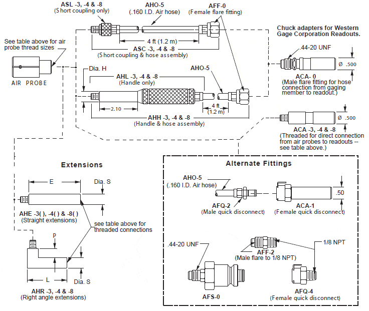
Accessories for Air Probe – Dual Master – Series 10 thru 50
| AIR GAGE SIZE ABOVE-INCL |
DASH NO. |
THREAD SIZE |
HANDLE Dia. H |
(EXTENSION DIMENSIONS) | (EXTENSION PART NO.S) | |||
| Dia. S | L | P | DIM E = 4 in. | DIM E = 6 in. | ||||
| .059-.120 | -3 | #10-32 UNF | .287″ | .312″ | 1.62″ | .38″ | AHE -34 | AHE -36 |
| .120-.300 | -4 | .25-28 UNF | .437″ | .437″ | 1.62″ | .38″ | AHE -44 | AHE -46 |
| .300-.485 | -3 | #10-32 UNF | .287″ | .312″ | 1.62″ | .38″ | AHE -34 | AHE -36 |
| .485-.860 | -4 | .25-28 UNF | .437″ | .437″ | 1.62″ | .38″ | AHE -44 | AHE -46 |
| .860-UP | -8 | .50-20 UNF | .812″ | .750″ | 1.75″ | .25″ | AHE -84 | AHE -86 |
SERIES 10 THRU 50
AHH-3 Handle & hose – #10-32 UNF
AHH-4 Handle & hose – .25-28 UNF
AHH-8 Handle & hose – .50-20 UNF
AHL-3 Handle only — #10-32 UNF
AHL-4 Handle only — .25-28 UNF
AHL-8 Handle only — .50-20 UNF
ASC-3 Short coupl’g & hose – #10-32 UNF
ASC-4 Short coupl’g & hose – .25-28 UNF
ASC-8 Short coupl’g & hose – .50-20 UNF
ASL-3 Short coupling only — #10-32 UNF
ASL-4 Short coupling only — .25-28 UNF
ASL-8 Short coupling only — .50-20 UNF
AHE-34 Extension, 4 in. – #10-32 UNF
AHE-36 Extension, 6 in. – #10-32 UNF
AHE-44 Extension, 4 in. – .25-28 UNF
AHE-46 Extension, 6 in. – .25-28 UNF
AHE-84 Extension, 4 in. – .50-20 UNF
AHE-86 Extension, 6 in. – .50-20 UNF
AHR-3 Rt. Angle adapter – #10-32 UNF
AHR-4 Rt. Angle adapter – .25-28 UNF
AHR-8 Rt. Angle adapter – .50-20 UNF
COMPARATOR FITTINGS
ACA-0 Chuck adapter — male flare
ACA-1 Chuck adapter, quick disconnect
ACA-3 Chuck adapter — #10-32 UNF
ACA-4 Chuck adapter — .25-28 UNF
ACA-8 Chuck adapter — .50-20 UNF
ACA-9 Chuck adapter, male flare w/bleed
AFS-0 Set lock adapter, male flare
AFF-2 Male flare — 1/8 NPT
REPAIR PARTS
AHO-2 4.0mm Air hose only ( Metro )
AHO-4 .125 Air hose only
AHO-5 .160 Air hose only
AFF-0 Female flare – .160 hose barb
AOR-3 O-rings for – 3 accessories, 10 pcs
AOR-4 O-rings for – 4 accessories, 10 pcs
AOR-8 O-rings for – 8 accessories, 10 pcs
ACF-10 Chuck Nut & Brass Collet


